Der vil blive pakket ordre den 22/12, 23/12, 29/12, og den 30/12. Vi ønsker alle en god jul, og et godt nytår. :)
kr.135.00 inkl. moms
LilyPad ATmega32U4 Udviklingsboard.
USB Type: Micro-B USB stik
På lager
LilyPad ATmega32U4 Udviklingsboard er et lille board, som kan bruges til de helt små projekter, hvor pladsen ikke er der. Ledninger kan også loddes på.
Denne ATmega32U4 chip skal ingen driver bruge.
| Microcontroller | ATmega32u4 (Bruger ingen driver) |
| Operating Voltage | 3.3V |
| Input Voltage | 3.8V-5V |
| Digital I/O Pins | 9 |
| PWM Channels | 4 |
| Analog Input Channels | 4 |
| DC Current per I/O Pin | 40 mA |
| Flash Memory | 32 KB (ATmega32u4) of which 4 KB used by bootloader |
| SRAM | 2.5 KB (ATmega32u4) |
| EEPROM | 1 KB (ATmega32u4) |
| Clock Speed | 8 MHz |
Før du kan starte din programmering skal Arduino’s IDE software hentes. Dette program bruges til at programmere din arduino.
Download fra dette link: Download
Før du kan starte din programmering skal Arduino’s IDE software hentes. Dette program bruges til at programmere chippen.
Download fra dette link: Downlaod
Inden programmeringen kan udføres skal den rigtige “COM” port findes. Klik “Værktøj/Port” – og vælg COM port.
Inden koden skal uploades skal arduinos software vide at koden skal programmeres til en “Arduino Pro” klik på “Værktøj – Board” og find “Arduino Leonardo”
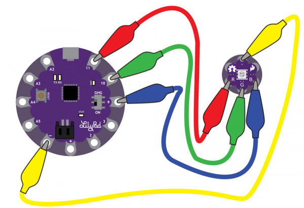
Her viser vi et hurtig eksempel på hvordan du kan starte din første projekt. Dette eksempel får en simpel LED Diode til at blinke.
Du skal bruge:
Forbind det sådan:
/*
LilyPad Tri-Color LED: Basic Color Mixing
Written by: Gella and Ho Yun "Bobby" Chan
SparkFun Electronics
https://www.sparkfun.com/products/13735

Create primary and secondary colors on the tri-color (Red/Green/Blue)
LED connected to a LilyPad Arduino.

Tri-Color LED connections:
R pin to 11
G pin to 10
B pin to 9
- pin to -


This code is released under the MIT License (http://opensource.org/licenses/MIT)

******************************************************************************/

// This example uses a tri-color, also known as an RGB
// (Red / Green / Blue) LED.
// This example uses digitalWrite() to turn the three LEDs on and off
// in various combinations to create eight primary and secondary colors.

//debug mode, comment one of these lines out using a syntax for a single line comment: //
#define DEBUG 0 //0 = LEDs only
//#define DEBUG 1 //1 = LEDs w/ serial output

// Create integer variables for our LED pins:
#define RGB_red 11
#define RGB_green 10
#define RGB_blue 9

void setup() {

// Make all of our LED pins outputs:
pinMode(RGB_red, OUTPUT);
pinMode(RGB_green, OUTPUT);
pinMode(RGB_blue, OUTPUT);

#if DEBUG
Serial.begin(9600); //initialize Serial Monitor
//while (!Serial); // Comment out to wait for serial port to connect to Serial Monitor. Needed for native USB.
Serial.println("Basic Color Mixing w/ a Common Cathode RGB LED");
#endif

}//end setup()

void loop() {

// This code will step through the six primary and secondary colors, plus white and black.
// Note: for this particular LED, the wiring shares a common anode (+), which means to
// turn on the LEDs you will set them LOW instead of HIGH.
// Keep this in mind as you prototype with the LED and mix your colors.

// For each of these colors, we'll turn the necessary RGB LEDs on or off.


// Black (all LEDs off)
// RGB LEDs:
#if DEBUG
Serial.println("OFF");
#endif
digitalWrite(RGB_red, LOW);
digitalWrite(RGB_green, LOW);
digitalWrite(RGB_blue, LOW);
delay(1000);

// Red (red LED on)
#if DEBUG
Serial.println("RED");
#endif
digitalWrite(RGB_red, HIGH);
digitalWrite(RGB_green, LOW);
digitalWrite(RGB_blue, LOW);
delay(1000);

//Yellow (red and green LEDs on)
#if DEBUG
Serial.println("YELLOW");
#endif
digitalWrite(RGB_red, HIGH);
digitalWrite(RGB_green, HIGH);
digitalWrite(RGB_blue, LOW);
delay(1000);

// Green (green LED on)
#if DEBUG
Serial.println("GREEN");
#endif
digitalWrite(RGB_red, LOW);
digitalWrite(RGB_green, HIGH);
digitalWrite(RGB_blue, LOW);
delay(1000);

// Cyan (blue and green LEDs on)
#if DEBUG
Serial.println("CYAN");
#endif
digitalWrite(RGB_red, LOW);
digitalWrite(RGB_green, HIGH);
digitalWrite(RGB_blue, HIGH);
delay(1000);

// Blue (blue LED on)
#if DEBUG
Serial.println("BLUE");
#endif
digitalWrite(RGB_red, LOW);
digitalWrite(RGB_green, LOW);
digitalWrite(RGB_blue, HIGH);
delay(1000);

// Magenta (red and blue LEDs on)
#if DEBUG
Serial.println("MAGENTA");
#endif
digitalWrite(RGB_red, HIGH);
digitalWrite(RGB_green, LOW);
digitalWrite(RGB_blue, HIGH);
delay(1000);

// White (all LEDs on)
#if DEBUG
Serial.println("WHITE");
#endif
digitalWrite(RGB_red, HIGH);
digitalWrite(RGB_green, HIGH);
digitalWrite(RGB_blue, HIGH);
delay(1000);

}//end loop
Du er altid velkommen til at kontakte os på info@ardustore.dk, eller sende os en besked via messenger (Klik her) og vi vil hjælpe dig.
På lager
Tilføj til kurv
På lager
Tilføj til kurv
På lager
Tilføj til kurv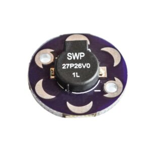
På lager
Tilføj til kurv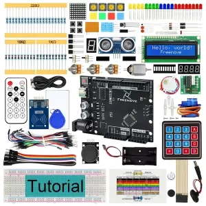
Udsolgt - Send mail
Læs mere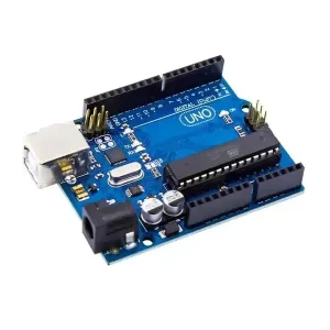
På lager
Tilføj til kurv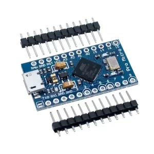
På lager
Vælg muligheder Dette vare har flere varianter. Mulighederne kan vælges på varesiden
På lager
Vælg muligheder Dette vare har flere varianter. Mulighederne kan vælges på varesidenTelefonen har åben:
Mandag – Fredag 07.00 – 16.00
Kontakt os:
Mail: info@ardustore.dk
Telefon: 41403333
Virksomheden:
Ardustore.dk
Klinkbjerg 4B
6200 Åbenrå
CVR: 39973804
Afhentning: Ordren som afhentes bliver lagt i postkassen som er låst med en kode. Koden kommer i den mail som sendes når pakken kan afhentes. Vores postkasse er på væggen i gården.
Vi er meget mere ind bare en webshop, vi tilbyder også forskellige service.
– Udvikling af egen PCB print
– Salg af komplet styringer
– Software udvikling
– Programmering
– 3D Design af kasser
Skriv til os på info@ardustore.dk
Vi vil prøve noget nyt! Der findes ingen sider i Danmark som tilbyder forums inde for Arduino! Derfor har vi prøvet at lave et lille univers for Arduino entusiaster.


Telefonen har åben:
Mandag – Fredag 07.00 – 16.00
Kontakt os:
Mail: info@ardustore.dk
Telefon: 41403333
Virksomheden:
Ardustore.dk
Klinkbjerg 4B
6200 Åbenrå
CVR: 39973804
Webshoppen er ikke en butik som kan besøges. Men det er muligt at afhente ordre, dog efter aftale via mail eller tlf. (Også i weekenden)
Afhentning: Ordren som afhentes bliver lagt i postkassen som er låst med en kode. Koden kommer i den mail som sendes når pakken kan afhentes.
Vi er meget mere ind bare en webshop, vi tilbyder også forskellige service.
– Udvikling af egen PCB print
– Salg af komplet styringer
– Software udvikling
– Programmering
– 3D Design af kasser
Skriv til os på info@ardustore.dk
Vi vil prøve noget nyt! Der findes ingen sider i Danmark som tilbyder forums inde for Arduino! Derfor har vi prøvet at lave et lille univers for Arduino entusiaster.


Anmeldelser
Der er endnu ikke nogle anmeldelser.